
Mechanism of the Clamp
Principle of the Clamp
The initial load — consisting of the clamp’s own weight and the spring force of the lock device — causes the cam and the swivel jaw to clamp the load, creating initial friction that initiates lifting or tilting.
As the load increases, the link mechanism provides a leverage effect, and the cam mechanism applies an automatic tightening action, increasing the clamping force until the cam bites into the load.
Even if the clamp is temporarily unloaded during a turning operation, the lock device keeps pressing the cam by the force of the spring.
Main Structure and Features
Structure of the Clamp
- The clamp works by the weight of the load.
The cam (toothed plate) and the swivel jaw, made from our original steel and properly heat-treated, bite into the load to lift it. - The clamp has cam and link shapes designed so that the clamping force is stable even when the plate thickness or lifting angle changes.
(※Be careful when clamping steel plates with a thickness of less than one-quarter of the maximum applicable plate thickness or loads of less than one-fifth of the Working Load Limit (WLL).) - The clamp is equipped with a lock device or a lock spring (except some models such as the Model VA).
While the lock device is locked, even during a temporary no-load state when turning over or landing, the clamp is less likely to come off, reducing the risk of accidental release.

Typical Failures from Continuous Use
- Wear or chipping of cam (toothed plate)
- Wear or chipping of swivel jaw
- Loss of spring force, damage, or deformation
- Wear of pin, pin hole, or pin groove
- Deformation of link
- Metal fatigue, dents, wear, or deformation of the main body
- Deformation of lifting shackle
- Wear of screw or screw hole
- Deformation or damage of components due to overload
- Malfunction and reduced clamping force due to lack of lubrication
The cam (toothed plate) and the swivel jaw wear with use.
If the wear exceeds the service limit, the friction may decrease depending on the surface condition of the load, and the load may slip off.
Proper inspection and maintenance are required for safe operation.
Lock Devices
Eagle Clamp’s lock devices are available in latch type and lever type.
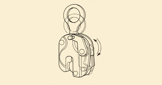
Latch Type Lock Device (Spring Clamping Mechanism)
When the latch for the lock device is pushed into the body, the spring force works to push the clamping cam out to the opening, pressing it against the load.
When not in use, the spring is not engaged, so the clamping cam can open and close freely, and it is linked to the lifting shackle.
In normal operation with the spring engaged, the clamping cam does not open.
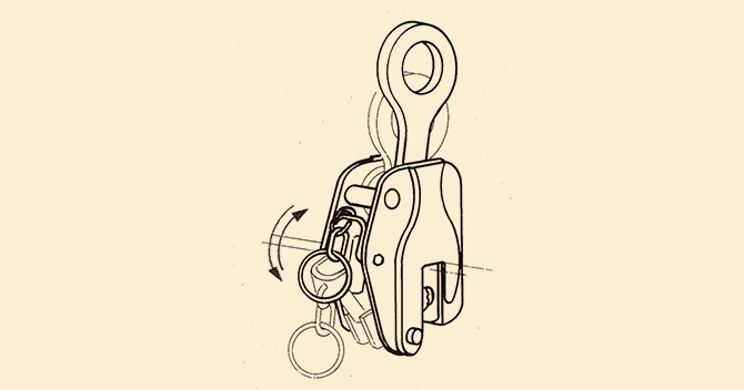
Lever Type Lock Device (Clamping and Release Mechanism)
[Clamping Mode]
When the lever for the lock device is set to the locked position, the spring force works to push the clamping cam against the load.
Even if the clamp is momentarily unloaded, the clamping cam does not open while the lock device is locked.
[Release Mode]
To remove the clamp, set the lever to the unlock position.
In this position, the clamping cam does not close even when the lifting shackle is pulled.
Types of Clamps
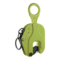 Vertical Lifting Clamp
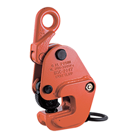 Lateral Lifting Clamp
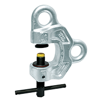 Screw Clamp
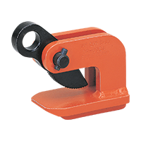 Horizontal Lifting Clamp
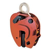 Non-Marring Clamp
Vertical Lifting Clamp
The toothed cam and the swivel jaw clamp the load.
The lock device presses the cam against the load with spring force.
The clamping force is proportional to the working load.

- ※ The force (F) applied to the lifting shackle is transferred to the cam through the link.
The force (f) applied to the cam, pivoted on the cam pin, clamps the load as the clamping force (f).
Vertical Lifting Operation

Lateral Lifting Clamp
The toothed cam and the swivel jaw clamp the load.
The lock device presses the cam against the load with spring force.
The clamping force is proportional to the working load.

- ※ The force (F) applied to the lifting shackle is transferred to the cam through the link.
The clamping force (f), pivoting on the cam pin, clamps the load.
Lateral Lifting Operation (Model G)

Screw Clamp
When the load is applied, the spherical jaw tilts and embeds into the load to grip it.
This structure allows lifting in any direction.

- ※ When lifting or pulling as shown in the figure, the spherical jaw tilts by the friction from the clamping force by the screw and by the lifting load (W), generating the clamping force (P).
The clamping force is approximately two to three times the lifting load.
Horizontal Lifting Clamp
The conventional “Hacker,” used for horizontal transport, can be unstable due to tilting or vertical impacts.
To eliminate this instability, this clamp is designed to hold the load from above.
The holding force is proportional to the lifting load.

- ※ The force (F) applied to the lifting hole is transferred directly to the cam.
That force clamps the load as the clamping force (f), pivoted on the cam pin.
Non-Marring Clamp
To prevent damage to the load, this clamp grips it with a flat pressure plate and a support plate.
For additional safety, the stopper cam is built in.
The clamping force is more than five times the load weight.

- ※ The opening is adjusted with a wedge to match the thickness of the load.
The load applied to the lifting shackle is converted into clamping force (f) by the L-link and the clamping arm.
(Model NE, Model BMB)
Clamp Selection Points
Clamps are classified according to their application and structure.
Cam-type clamps include vertical lifting clamps, lateral lifting clamps, and horizontal lifting clamps. Non-marring models are also available for both vertical and lateral lifting clamps.
In addition, there are screw clamps and special clamps for specific loads or operations.
1. Selection of Type and Model
Select the type (e.g., for vertical lifting) and model (e.g., Model E) according to the application and the lifting loads, such as steel plates or structural steel.
2. Selection of Working Load and Applicable Plate Thickness
Select the working load according to the weight of the load and the number of lifting points, and select the applicable plate thickness according to the plate thickness of the load and the width of the attachment section.
- ※The mechanisms and principles of the clamps apply only to the proper use of clamps for steel materials.
Before use, be sure to check the instruction manual for each product.
For clamps for concrete products, refer to the dedicated catalog or instruction manual.